Application of SEL Intelligent Instrument in Xiahui Pit Power Station
1 Introduction The installed capacity of the Xiahang Hydropower Station in Shangrao, Jiangxi province is 2x8MW. Electrical energy is sent to the county power grid via a 35kV line once and to Huazhong Power Grid on a 110kV line. The power station serves as the frequency-modulating peaking task in the county power grid. The main wiring form of the power station is: two-phase two-transformation double busbar wiring, the generator outlet voltage is 6.3kV, and the single busbar is segmented by the isolating switch; the main transformer is 2 sets, and the capacity is both IOMVA. The Xiakeng Hydropower Station 2x8MW unit is connected to the 110kV bus and the 35kV bus of the power station through a double-winding transformer and a three-volume transformer. The power station is equipped with two sets of transformers, which are connected to the I and II sections of the 6.3 kV bus.
2 Protection Configuration In this system, we use SEL series microcomputer protection devices and communication processors manufactured by SCHWEITZER ENGINEERING LABORATORIES, INC. to protect and monitor the line and main transformer.
Various types of SEL series microcomputer protection devices are suitable for various different power devices. Their characteristic lies in that SELogic control equations can be used to complete the control programming output of the protection opening and output and other logic, to flexibly realize the required protection function, and to make the protection more adaptable; to use an unequal number of serials. The communication port can effectively transmit key information including measurement data, protection element and contact I/O status, event report, circuit breaker monitoring and clock synchronization.
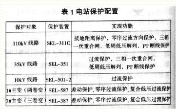
The protection configuration and functions adopted in the Xiaheng Power Plant are shown in Table 1.
3 System Architecture 3.1 Analysis of the Functional Characteristics of the SEL-2020 Communications Processor (1) The SEL-2020 communications processor is equipped with 16 EIA-232 backplane serial ports labeled “PORTI†through “PORTl6†and a "PORTF" EIA-232 panel serial port. In addition to PORTF can only be used to communicate with the host device, the other 16 serial ports can be selected and SEL relay (SELIDE), other suppliers of intelligent electronic equipment (OTHERIDE), serial printer (PRINTER) or host device (MASTER), Including RTU, PC, NlM or ASCII non-intelligent terminal communication. Can be built-in modem at PORT8 mouth, can also point out point and point the optic fibre Modem or telephone line to dial Mordem outside any backboard serial port, use for exhaling to a distant PC or lED.
This feature can be used to automatically transfer data from the SEL-2020 database to a remote location or to collect data from a remote device.
(2) These ports support multiple communication protocols. If the port is set to connect MASTER, the optional protocols are SEL, LMD (all ports), Modbus (ports 12, 14, 16) and DNP (port 16).
(3) The SEL-2020 can handle the operation of all ports concurrently. This allows multiple users to communicate with the SEL-2020 or the SEL-2020 at the same time. Other operations such as printing, dial-out of the modem can be performed simultaneously on other ports. Wait.
(4) The SEL-2020's internal database can store status information and data collected from devices connected to the backplane ports. The data area consists of 16 backplane communication port databases. Each port database can contain up to 15 data areas, including GLOBAL, LO-CAL, BUF, 8 data areas (D1-D8), 3 archives Area (Al-A3) and User Data Area (USER).
The global zone contains data common to all ports, including SEL-2020 status and configuration information, global components, and so on; local zones contain different information for each port, including status and configuration information, local components, and special command registers (SBO and CMD ) Etc.; BUF area caches unsolicited packets received from the port by SEL-2020; data area is used to store the data received and parsed by the SEL-2020 port, each data area is associated with a data request created by the SETA command. Corresponding to the message string, the response message of the corresponding sent message is stored; the USER area is defined by the user and can be written from the host device using the STORE command or the special user-defined command WRITE, or can be written by the SETM command. The data in other data areas is copied to this area, and the data is collected and reorganized so that other ports can use these data to create messages.
(5) The SEL-2020 can receive, buffer, and analyze data and can respond to these data. You can request data from the device connected to the port by sending a standard message or a custom message from the SEL-2020, or control the response initiated by the message. You can also set the port to automatically accept and resolve unsolicited data. In addition to the control in the communication program, the logic conditions of the trigger message can be flexibly set using the SELLogic equation described later.
3.2SELOGIC logic control equation In addition to the above features, SELOGIC control equation is also a major feature of SEL series smart meters. The equations consist of global elements, local elements, relay elements, relay status information, arbitrary database bits, and time conditions. This information is logically connected to (*), or (+), and negation (!) to represent simple to complex logical relationships. The SELOGIC control equations can be flexibly used according to actual requirements, and logical conditions can be programmed to trigger control contact output and automatic message triggering, which greatly improves the system's adaptability. Two problems encountered in the development and debugging process are quickly solved using SELOGIC control equations.
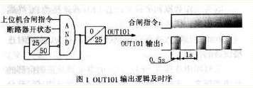
(1) In the 110kV line protection device SEL-311C, the 1# output port OUTl01 is set to respond to the closing command of the PLC and issue a circuit breaker closing signal. This signal is blocked by the breaker status, which allows OUT101 to signal when the breaker status is OFF. When debugging the SEL-311C, it was found that if the host computer does not consider other conditions, as long as the closed condition is satisfied, a high level command is issued, and the actual circuit breaker cannot be closed, the OUT101 port will repeatedly issue a signal to make the intermediate relay jump. Pull arc.
In response to this situation, we used the SELogic equation to modify the output logic of the OUT101 port, as shown in Figure 1. In the above situation, the output of OUT101 is in the form of square wave, which avoids the occurrence of consecutive jumps. The box in the logic diagram represents the timer, the upper left digit is the holding time, the lower right digit is the duration, and the unit is the weekly wave. The correlation equation is as follows:
SV2PU=25;SV2DO=50;SV6PU=O;SV6DO=25;// Set timer time SV2=OUT101;SV6=IN102+IN103;//Set timer condition OUT101=SV6T*!IN101•!SV2T//Set OUT101 output logic
The correlation equation is as follows:
SIVlPU = 225; SIVIDO = 2; SIV2PU = 25; S2V2DO = 2; / / set the timer time S1V1 = 50N11T; S1V2 = S1V1T; / / set the timer condition OUT101 = 87U + 87R + IN1O1 + S1V2T / set OUT101 output Logic OUT107=S1V1T// Setting OUT107 Port Output Logic Although the logic of the above two cases is simple, it can reflect the SELogic's flexibility, convenience, and adaptability.
3.3 Several Application Programs Through the analysis of the SEL-2020 communications processor's functional characteristics, we found that the SEL-2020's communication processing capabilities and database capabilities enable it to collect data from various devices and analyze the data into useful parts. Distribute the required data to other devices and systems. This is the basic idea of ​​substation automation. The SEL-2020's network capabilities allow it to serve as an integrated communications network for small substation project data, and as a sub-network intensive device in large substation networks. From this, it is possible to imagine the construction of several underlying relay network protection systems for MCUs based on SEL-2020.
Solution One: The SEL-2020 is used as a data concentrator to receive RTU enquiries and controls. The SEL-2020 connects the SEL relay protection devices and other smart meters on the site, and connects the RTU to the Modem on Port 8. Port9 connects to the printer, PortF connects to the local terminal, and IRIG-B connects to the clock source.
The system completes the following tasks:
1 Synchronize all IEDs with the IRIG-B clock source.
2 Obtain the working data and accident report of the connected equipment by reply message or unsolicited automatic message.
3 Analyze the acquired data and store it in the database data area and user area according to a predefined format.
4 Communication with the RTU via a built-in or external modem.
5 Display working data and accidents on the LED or connected PC terminal for on-site personnel to view.
6 The control message is triggered by keyboard input or predetermined logic to control the connected device.
7 Prints all unsolicited messages sent by the relay connected to the SEL-2020. This is a very simple and economical substation approach that takes full advantage of the SEL-2020's data processing, automatic database, logic and communication capabilities.
In this system, the data of each port relay is polled by the SEL-2020 cycle and parsed into each port database and user-defined database to ensure real-time data. If the data communication between the SEL-2020 and the RTU adopts an active method, it can be defined that the SEL-2020 automatically sends a data message cyclically according to a predetermined protocol for the RTU to receive; if the passive method is adopted, the RTU query message is set as a trigger condition. The SEL-2020 responds and sends a reply message according to a predetermined protocol. The RTU also controls the port relays via the SEL-2020. For this purpose, the RTU control message is used as the trigger condition, and the SEL-2020 responds by sending a quick operation command to the port relay to change the state of the related word bit of the relay.
The fast operation command is a short message binary command that enables the SEL relay to execute the relevant command within 16 ms of receiving the message. At the same time, the logic is set in each port relay so that the relevant word-position change corresponds to the corresponding relay action, such as jumping and closing.
Solution 2: Receive data from the SEL series connected to the SEL-2020 port and various other non-SEL intelligent electronic devices (IEDs), and provide runtime data and event reports to the local control unit (LCU); accept LCU control commands , Send a corresponding control message to the connected IED. If necessary, multiple host devices such as PC and RTU PLC can be connected at the same time to exchange data between these industrial control devices and the underlying IED.
Since the SEL-2020 can customize the message string, as long as there is a complete command set for the device, regardless of the communication format used by the device, the SEL-2020 can be set to communicate with the IED with the RS-232 interface, and the received data will be received. After parsing into the database. By independently setting each port of the SEL-2020, the SEL-2020 can handle the operation of devices connected to each port concurrently with different communication protocols or communication formats.
This structure can be used as a complete network subnet, and the SEL-2020 is connected to the main network bus. At this time, the SEL-2020 plays a role as a relatively independent part of IDE and host equipment. At the same time, the SEL-2020 communicates with IDEs and host devices of different communication protocols and can solve some protocol compatibility problems. For small automation systems, it may also be considered to use this structure directly to simplify the design and installation.
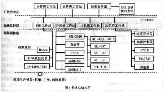
Solution 3: Basic application method, using the SEL-2020 as a data concentration device for the SEL equipment, functions as port switching, data transmission, analysis, processing, and storage, and synchronizes the clock of the connected device, and also serves as the serial communication of the field measurement and control layer. A node on the network bus, or an extended serial port connected to the LCU. This project took this approach. The station level supervisory layer and the factory level management layer selects IEEE802.3 standard Ethernet and adopts the standard MODBUS agreement, forms the complete distributed distributed control system. Microcomputer relay protection device forms the monitoring and control subnet with SEL-2020 as the core, and access system through SEL-2020.
The overall network structure of the system and the position of the microcomputer relay protection system are shown in Figure 2.
Using the features of the SEL-2020, you can also combine multiple application scenarios. In fact, with the development of industrial control technology in the direction of decentralization, networking, and openness, the functions of smart meters such as SEL-2020 communications processors and SEL protection devices have been continuously strengthened, and control functions have been increasingly released underground. Instrumentation equipment, the degree of decentralized control of the system is getting higher and higher. This allows designers to expand their thinking and have more choices.
4 Communication Program Implementation In this system, the SEL-2020 communicates with the host computer as a Modbus slave. The Modbus protocol is a reliable and effective industrial control system communication protocol designed by GOULD for industrial control. It is supported by many hardware manufacturers including Simon, Honeywell, PML, and many other RTUs and most PLC or PLC networks. compatible. The physical layer of Modbus uses RS-232 mode. RS-232 is an electrical standard developed by the Electronic Industries Association (EIA) as a serial communication interface, and the corresponding international standard is defined by CCITF. 24 interface.
The Modbus data transmission is master/slave. The message format is request/response frame.
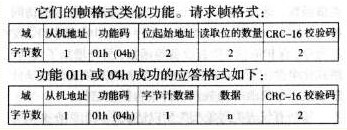
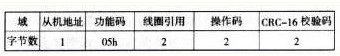
The data request packet of the Modbus data link layer consists of an address, a function code, data, and a check code, and the type of data exchange is controlled by a function number (FCs). If the operation is successful, the format of the reply message is the same as that of the request message. If an error occurs, the reply message sets the function code height.
The function codes supported by the SEL-2020 are: 01 (read coil status), 02 (read input status), 03 (read hold register), 04 (read input register,) 05 (constrained single coil) 06 (set single coil) 10 (Set multiple coils), 11 (Report slave ID). Which commonly used 01 and 04 function code to read data from the SEL-2020, use 05 function code to achieve data control, such as control circuit breakers and remote control bit components.
Function code 01h to read the status of various bits. Up to 1000 bits can be read at a time; function code 04h is used to read the Modbus specified memory image, allowing the user to read 125 registers at a time.
Know that:
1 The common characteristics of all the instruments in the system are extracted, such as the serial number, instrument type number, slave address, function description, etc., to form the meter base class CMeter as the parent class of each type of smart meter abstract class. The CMeter class also defines a set of standard instrument access and data access interfaces, which are given in the form of virtual functions. Each inherited subclass (ie, each instrument class) implements its operations.
2 serial port class CCom class provides serial port initialization and read / write interface, using CCom as a parent class further derived a standard communication protocol class CModbus, on the basis of serial data receiving / sending, increase the buffer, frame, unpack, CRC Functions such as checksum and function code processing and corresponding data structures are used for the construction and analysis of Modbus protocol frames.
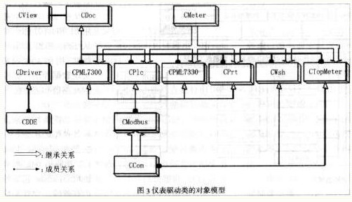
4 All instrument class objects are organized by type in a linked list in the document class CDoc, which serves as the basis for the operation of the driver. The driver class CDriver creates a data collection thread, passes the pointer object list through the pointer, invokes the instrument class interface to obtain the data read/write control of the physical instrument, and at the same time implements the DDE callback function and establishes the DDE communication connection through its CDDE class object.
5 Concluding remarks This article discusses the application of intelligent instruments such as SEL series communication processors and microcomputer protection devices at Shanghang Raohui Power Plant in Jiangxi Province. At the same time, based on the analysis of the SEL-2020 communications processor, it provides a variety of flexible applications for a variety of applications. Ideas. In the context of the development of industrial control technologies in the direction of decentralization, networking, and openness, the data processing and communication functions of various smart meters have been continuously enhanced, so the above research has certain reference significance. The system is stable and reliable in actual operation, and it meets system design requirements in terms of reliability and accuracy of protection actions, communication response time, and data transmission accuracy.
APPLICATION FEATURES
1. Environment:The bearing is located in the lower part of the chassis, normally working in a dusty and mud splash environment, so it is with high requirement of bearing sealing performance. Working in outside, from low temperature -40 ℃ to high temperature 100℃;
2. Rotating speed: Highest is 3000rpm;
3. Loading: Besides to bear the weight of the main rotating axis, also need to bear the uncertain axial load;
4. Eccentric Oblique angle:Bearing is used with propeller shaft(or drive shaft), need consider to compensate the installation error of the shaft, and the displacement caused by the engine vibration and frame deformation, so the oblique angle of bearing are key factor to be paid attention during bearing design.
Drive Shaft Bearings,Drive Shaft Carrier Bearing,Drive Shaft Wheel Bearing,Drive Shaft Center Support Bearing
ZHEJIANG XCC GROUP CO.,LTD. , http://www.xccbearing.com