Flame detector classification
 With the development of science, people gradually realized the flame, and at the same time invented the flame-detector, a tool for understanding the flame. It is mainly composed of a probe and a signal processor.
 Flame detector classification:
1. Ultraviolet Flame Detector The ultraviolet flame detector uses a UV photodiode as the sensing element, and its spectral range is between O.006 and 0.4?m. The ultraviolet phototransistor is a solid-state pulse device. The signal emitted by the device is a random pulse whose frequency is directly proportional to the frequency of ultraviolet radiation. The UV photo-sensitive tube has two electrodes, generally with ac high voltage. When the UV rays radiated to the electrodes are sufficiently strong, an "avalanche" pulsed current is generated between the electrodes, the frequency of which is related to the intensity of the ultraviolet rays, up to several kilohertz. No pulse when extinguishing.
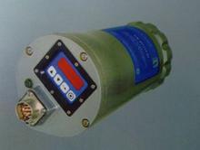
2. Visible light flame detector The visible light flame detector uses a photodiode as the sensing element, and its spectral response range is between 0.33 and 0.7 μm. The visible light flame detector consists of a probe, a chassis, and a cooling device. The visible light in the furnace flame passes through the lens at the end of the probe, passes through the optical fiber to the probe chamber, and strikes the photodiode.
The photodiode converts the visible light signal into a current signal and converts it into a voltage signal via a logarithmic amplifier. The voltage signal output from the logarithmic amplifier is converted into a current signal through the transmission amplifier. Then it is transmitted to the chassis through a shielded cable. In the chassis, the current signal is converted into a voltage signal. The voltage signals representing the flame are sent to the frequency detection circuit, the intensity detection circuit and the fault detection circuit, respectively. The strength detection circuit is provided with two different limits, the upper limit and the lower limit. When the flame intensity exceeds the upper limit value, the intensity lamp lights up to indicate ignition; when the intensity falls below the lower limit value, the intensity lamp goes off, indicating that the fire is extinguished.
The frequency detection circuit is used to detect the flame frequency of the furnace flame. According to whether the frequency of the flame of the flame is higher or lower than the set frequency, the frequency of the flame can be correctly judged whether there is a flame in the furnace. The fault detection circuit also has two limits. Under normal conditions, the value is maintained between the upper and lower limit values. Once the signal input circuit of the chassis fails, such as the disconnection of the cable from the photocell to the chassis, the above voltage signal immediately deviates from the normal range and a fault alarm signal is issued.
3, infrared light flame detector infrared light flame detector using lead sulfide or cadmium sulfide photosensitive resistance as a sensing element, its spectral response range between 0.7-3.2? m. The infrared light flame detector is also composed of a probe, a chassis, and a cooling device. The infrared radiation generated by the primary combustion zone of the burner flame is sent to the probe via the optical fiber, converted into an electrical signal by the photo-resistor in the probe, and then amplified by the amplifier. The flame signal is sent from the shielded cable to the chassis, through the frequency response switch and an amplifier, and then compared with a reference voltage (adjustable).
If the flame signal is greater than the reference signal, the corresponding trigger is set to "1", and the trigger output signal is sent to the flame detection circuit so that the red flame indicator in the chassis lights up (indicating a fire). On the other hand, if the probe does not detect a flame, a 3.5s timer is started. When 3.5s expires, the above trigger is set to “0â€. The trigger output signal is sent to the flame detection circuit to make the red flame indication inside the chassis. The light goes out (indicating fire extinguishing). 2.4 Flame Image Detector.
The flame image detector is a new product that appeared in the 1980s. The flame image detector is mainly composed of optical fiber, video camera (CCD), video input processor, image memory and computer.
Car Trumpet,Car Speaker,Car Snail Horn
Multi-Functional Wiper Blade Co., Ltd. , http://www.nscarhorn.com