Application of New Field Instruments in Key Operation Conditions of Chemical Plants
1 Introduction
In the modern production process, automation acquires, converts, displays, and transmits various kinds of information (process temperature, pressure, flow rate, composition, level of stationary equipment, interface, vibration amplitude of the rotating equipment, speed, etc.) through process detection instruments. Acceleration, rotation speed, displacement, etc.) After being processed by the process control system (DCS, ITCC, etc.), instructions are issued to control the control valve. The purpose of automation of the production process is to keep the process parameters at the required values ​​and the equipment is in optimal working condition. In terms of process instrumentation and regulating valves, they are like human "five features" and "four limbs." If the control parameters cannot be detected and adjusted effectively and accurately, the control becomes passive water and wood without a root.
Since the beginning of the 21st century, the development of new process detection instruments and control valves, represented by radar level gauges and labyrinth valves, has become more and more mature, and applications have become more widespread, especially in response to chemical engineering devices and to solve various complex, harsh and critical tasks. In the situation, remarkable results have been achieved.
2 radar level gauge
2.1 Measurement principle
As shown in Figure 1, taking a cable guided radar level gauge as an example, the measurement principle is based on the time travel, that is, the instrument measures the distance from the reference point (the instrument process connection) to the surface of the liquid level: the probe emits a high frequency radar. The wave propagates along the cable, and when the radar wave encounters the surface of the liquid level, it is reflected back by the receiver in the meter. Since the frequency of the signal is changing, the frequency of the echo is slightly different from the moment of signal transmission. The frequency difference is proportional to the distance to the liquid surface and can be calculated accurately, whereby the level height value is measured.
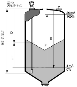
Fig. 1 Schematic diagram of radar level gauge measurement principle
2.2 Structural Features
1) Irrespective of factors such as medium density, temperature, pressure, etc., high measurement accuracy and wide application;
2) No moving parts, high reliability and maintenance-free;
3) According to the equipment requirements can choose a variety of installation methods, flexible and adaptable;
4) Parameters can be configured by various methods such as LCD head, handheld smart terminal, and computer software, which is convenient for debugging;
5) The use of dedicated software can complete the instrument configuration, data protection, signal analysis, file processing and other functions, analysis and diagnostic functions;
6) The electronic components are integrated in the display head, which can be disassembled and exchanged online, and the maintenance is convenient.
2.3 Application Case
In chemical production facilities, it is mainly used in four typical working conditions.
2.3.1 Liquid ammonia tank
2.3.1.1 Working Condition Overview
The actual case is a liquid ammonia storage tank 120-F for ammonia facilities, a vertical cylindrical tank with a height of about 23m, an inner diameter of about 21m, and a liquid ammonia with a design capacity of 5000m3. The design temperature is -33.3°C and the design pressure is 0.07MPa (gas phase). Floor).
The ammonia tank was previously used in-situ display with a steel belt level gauge (after due to heavy wear, frequent failures, high repair costs, has been disabled), and the use of differential pressure transmitter and external level gauge liquid The digital measurement signal is introduced into the DCS for display, and then a radar level gauge is added. The signal is introduced into the DCS display, and ESD is introduced at the same time. The differential pressure transmitter measurement signal constitutes a logic vote of 2oo2 to perform interlocking protection of the level.
2.3.1.2 Type Selection and Installation
E + H company's cable intelligent HART Guided Wave radar level gauge (FMP40 type), the process interface flange is DN40, pressure level is PN40, material is 316L, cable length 23.5m, diameter 6mm, material is 316, with Separate type display table (installed on the tank floor, cable length about 30m), measuring range is 20m.
The radar level gauge is installed on the top of the ammonia tank. A short pipe of DN150×2m is installed on the top of the cable, and the central ring is used to limit the position. The bottom probe is bolted to the bottom of the tank body and grounded.
2.3.1.3 Using Effects
The radar level gauge was installed and put into operation during ammonia tank cleaning during the system overhaul in March 2006. Its measurement signal was introduced into the DCS for display and alarm, and ESD was also introduced for interlock protection. The measurement is stable, normal, and reliable so far. Accurate, 2011 shows that the header fault has been replaced, and it basically belongs to maintenance-free status.
2.3.2 Boiler Drum
2.3.2.1 Working Condition Overview
The actual case is a boiler drum for a quick cooker, with a design temperature of 370°C and a design gauge pressure of 3.85 MPa (gas phase).
The drum used electrode type level switch, float switch and differential pressure transmitter to measure, alarm and interlock in the past, then cancelled electrode type liquid level switch, added rod type guided wave radar level gauge, adopted 2oo3 logical voting method. Low level interlock protection.
2.3.2.2 Type Selection and Installation
Using Rosemount's Smart HART Rod Guided Radar Level Gauge (3301HTHP), process interface flange DN50, pressure rating ANSI 600#, material 316, probe length 800mm, diameter 6mm, material 316, measuring range 500mm. The temperature-pressure curve of the high-temperature and high-pressure radar level gauge is shown in FIG. 2 .
The radar level gauge is installed in the bypass measurement cylinder and is constrained by a centering ring at the end of the probe.
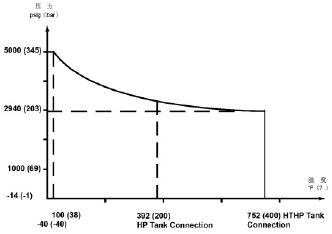
Fig. 2 Temperature-pressure curve diagram of Rosemount3301 series HTHP
2.3.2.3 Use effect
The radar level gauge was installed and put into use during the system overhaul in June 2007. The measurement has been stable, normal, reliable, and accurate so far and has not been overhauled.
2.3.3 Vacuum tank
2.3.3.1 Working Condition Overview
The actual case is a urea CO2 compressor surface condenser 905-C with a design temperature of 48°C and a design gauge pressure of -85 kPa (gas phase layer).
The ammonia tank used a pneumatic buoy type liquid level gauge to measure. Because it can not be used normally under high vacuum conditions, it was later changed to a radar level gauge and the measurement signal was introduced into DCS for display, alarm and interlock.
2.3.3.2 Type Selection and Installation
E+H company's intelligent HART cable guided wave radar level gauge (FMP40 type), process flange interface is DN50, pressure rating is ANSI150#, material is 316, probe length is 560mm, diameter is 6mm, material is 316, The measuring range is 550mm.
The radar level gauge is installed in the bypass measuring cylinder with a diameter of 2′′. The process interface is 1-1/2′′, and the center of the probe is limited by the centering ring.
2.3.3.3 Using Effects
The radar level gauge was installed and put into use during the system overhaul in August 2008. The measurement has been stable, normal, reliable, and accurate so far and has not been overhauled.
2.3.4 Crystalline media
2.3.4.1 Working Condition Overview
The actual case is the urea device S403/404 liquid level measurement, the medium is urine, the design temperature is 168 °C, and the design gauge pressure is 1.85 MPa (gas phase layer).
The ammonia tank used a double-flange liquid level transmitter to measure. Due to serious crystallization and inaccurate measurement, it was later changed to a rod-type guided wave radar level gauge.
2.3.4.2 Type Selection and Installation
E+H's Smart HART Rod Guided Wave Radar Level Gauge (FMP41C) with process flange interface DN50, pressure rating ANSI 300#, material 316L, probe length 1550mm, diameter 6mm, material 316L, The measuring range is 1300mm.
The radar level gauge is installed inside the bypass measuring cylinder with a diameter of 3′′ (jacketed steam heating trace), the process interface is 1-1/2′′, and the center of the probe is limited by the centering ring.
2.3.4.3 Using Effects
The radar level gauge was installed and put into operation during the system overhaul in May 2009. In 2011, dielectric leakage occurred due to the sealing of the probe and the display head, resulting in decreased insulation of coaxial connectors and corrosion of electronic components. After the rectification, it is operating normally. The measurement is stable, normal, reliable, and accurate so far. It basically belongs to the maintenance-free state.
3 labyrinth valve
In chemical plants, there are many severe working conditions such as high pressure difference and high flow rate. There are factors such as cavitation and flashing that cause great damage to the regulating valve. A multi-stage pressure reducing valve internal structure control valve such as a labyrinth valve is used. Can effectively solve such problems, and can obtain greater economic benefits.
3.1 Structural Features
In order to reduce the pressure drop and the flow rate of the two key factors, the internal structure of the labyrinth valve disc structure shown in Figure 3. Its features are:
1) A plurality of discs with labyrinthine flow channels are stacked. The labyrinth flow channels on each disc are processed into multi-level right-angled bends, and the high pressure difference is gradually decomposed. No matter how much the valve opening, the fluid can pass through each The flow rate of each channel is limited to 30m/s or less;
2) The entrance to the exit are designed to be small and large, which effectively prevents media particles from entering the flow path and blocking.
3) The labyrinth discs are alternately layered, and the lower disc outlet fluid lowers the speed of the upper layer downward flow media;
4) There is a file at the exit of the inner circle of each disk so that the pressure around the disk is even. The fluid at the outlet of the lower disk will not directly impact on the valve seat.
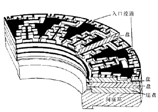
a) laminated labyrinth disc
b) Labyrinth flow
Figure 3 Labyrinth disc structure
3.2 Application Case
Since 2002, the company has successively used a large number of labyrinth valves to apply to a variety of adverse conditions, and has achieved good results and economic benefits. The following examples illustrate typical examples of venting conditions and cavitation conditions.
3.2.1 Venting conditions
3.2.1.1 Working Condition Overview
The actual case is the synthesis device 106-D inlet process gas vent valve PIVC-5, the pipe size is 12′′, the medium is the process gas, the design temperature is 318°C, the design pressure before the valve is 2.5MPa, and the gauge pressure after the valve is 0.2MPa. The maximum flow rate is 120t/h.
In the past, the vent valve used a pneumatic diaphragm direct-seat single-seat valve. Due to the large amount of leakage and serious wear of the valve trim, it was later changed to a labyrinth valve.
3.2.1.2 Selection
It adopts CCI's double-acting cylinder direct single-seat labyrinth valve (100D type) with a nominal diameter of 10′′, a pressure rating of ANSI 300#, a labyrinth disc of 410SS, and a leakage level of MSS-SP-61 (zero leakage).
3.2.1.3 Use effect
After the labyrinth valve was commissioned during the system overhaul in December 2002, a leak test was conducted to achieve a zero-leakage standard. After the installation, the temperature difference between the front and rear valves was measured to fully meet the requirements. Leakage tests were carried out during each subsequent overhaul, and they all reached the zero-leakage standard. The use of valve trims has not been performed until now.
The labyrinth valve has high adjustment accuracy, sensitive movement and extremely low leakage. According to the assessment and statistics, this valve has a loss of about 4.3 million square meters per year compared to the previously saved synthetic gas, which will increase the economic benefit by about 2.5 million yuan. In less than a year, the valve can recover the purchase cost.
3.2.2 Cavitation Condition
3.2.2.1 Working Condition Overview
The actual case is a synthetic ammonia unit 1101-E liquid level adjustment valve LV-91C, the pipe size is 18′′, the medium is AMDEA solution, the design temperature is 85.4°C, the design pressure before the valve is 2.75MPa, the gauge pressure after the valve is 0.97MPa, The maximum flow rate is 976t/h.
In the past, the vent valve used a pneumatic diaphragm direct-pass double seat valve. Due to the typical cavitation damage in this working condition, the valve internals were heavily scoured, the leakage amount was large, the failure rate was high, and the process requirements could not be satisfied. The labyrinth valve was later changed.
3.2.2.2 Selection
It adopts CCI's double acting cylinder straight single seat labyrinth valve (100D type) with a nominal diameter of 8′′ and a pressure rating of ANSI 300#. The labyrinth disc uses a 316SS surface hardened material with a leakage class of CLASSIV.
3.2.2.3 Using Effects
The labyrinth valve was commissioned and installed during the system overhaul in March 2006. It was inspected during each subsequent overhaul period and reached Class IV leakage standards. The valve trim was intact and has not been overhauled until now.
4 Conclusion
With the new type of field instruments such as radar level gauges and labyrinth valves, it is necessary to start with selection, installation, commissioning and many other aspects in order to make full use of them and ultimately achieve satisfactory results. The following is a summary of these two types of new field instruments in practical applications.
4.1 Radar Level Gauge
4.1.1 Selection
According to the physicochemical characteristics of the medium, different types of antenna types, such as contact type or non-contact type, whether high-temperature and high-pressure type are used, guided wave transmission adopts cable type, single rod type, double rod type, or coaxial type. For example, for liquid level measurement of drum boilers, it is recommended to select the coaxial type to overcome the influence of saturated steam in the vapor phase of the steam drum on the measurement.
4.1.2 Installation
According to the characteristics of the equipment to take different installation methods, such as the installation of holes directly in the equipment, or the use of bypass measurement tube installation, for direct installation in the equipment, we must pay attention to avoid the influence of the radar wave reflection transmission, the container wall, etc. For the installation of bypass measuring cylinders, consideration should be given to whether heating is provided and measures such as adding a centering ring are required.
4.1.3 Commissioning
During the debugging process, attention should be paid to the setting of the upper and lower dead zones, the choice of the container shape, whether the ground is connected, and the matching operation of the response curve of the empty cans. It is recommended to use dedicated software for debugging on the notebook computer, which is intuitive and clear and can acquire signal waveform diagrams.
4.1.4 Troubleshooting
Since the radar level gauge only has electronic components on the meter header, general faults are present here. After the diagnosis is confirmed, the indicator can be replaced directly online with the same model header. In addition, it should also pay attention to the coaxial interface connecting the probe, the insulation must be qualified.
4.2 Labyrinth valve
4.2.1 Selection
Before providing manufacturers with calculation and selection, it is necessary to ensure the integrity and correctness of the process conditions and parameters, because the selection of labyrinth valves is a harsh and demanding work environment with high pressure difference, high flow rate, and high sealing level. Generally come to block the flow phenomenon.
4.2.2 Commissioning
Leak test must be conducted before installation. Pipes can be installed after being qualified. If the leak test fails, besides recalibration, check whether the valve stem is eccentric. For example, the PIC-5 is due to the occurrence of transportation. Eccentricity, loosening the upper valve cover and then installing it again naturally, the leak test will pass.
4.2.3 Installation
Although the labyrinth flow path of the labyrinth valve disc was designed with the anti-clogging problem in mind, precautions should still be taken in practical applications. The first step is to install a mechanical filter in the upstream pipeline as much as possible, followed by a bypass valve. In this case, the labyrinth valve should be installed above the bypass valve. Finally, the pipeline should be purged before installing the pipeline.
4.2.4 Troubleshooting
In general, labyrinth discs are not easy to damage. Generally, there are particles and debris blocking the flow path. When removing, attention should be paid to reverse blowing. In addition, if the process does not reflect the problem, try not to open the valve trim. Only complete the valve leakage test, otherwise, after opening the valve trim and re-assembly, it will increase the probability of new failures.
The right laser cutting system for every requirement – from versatile fiber laser cutting machine in a range of formats and capacities capable of processing thin to thick ferrous and non-ferrous materials to high production Laser Tube Cutting Machines, all with performance-enhancing options, as well as CNC laser automation.
No matter the XUANLIN CNC Laser Cutting machine you choose, you are assured of reliable operation, consistent accuracy, and high control over the production process for top-quality laser cutting results.
Laser Cutting Machine,Laser Cutting Division,Cnc Laser,Fiber Laer,Fiber Laser Cutting,Laser Tube Cutting
JINAN XUANLIN MACHINERY CO., LTD. , https://www.cncfiberlaser.com