Mass flow sensor installation
1. Keep away from vibration sources
The sensor should be installed away from sources of interference that can cause mechanical vibration in the pipeline, such as on process lines.
Pumps and so on. If the sensors are used in series on the same pipeline, the mutual influence due to resonance should be prevented in particular. The distance between the sensors should be at least 3 times the width of the overall dimensions of the sensor.
2. Stay away from the expansion node
The installation position of the sensor should pay attention to the expansion and deformation of the process pipeline due to temperature changes, especially
Cannot be installed near expansion joints in the process pipeline. If it is installed near the expansion joint, the lateral stress will be caused due to the expansion and contraction of the pipeline, which will cause the sensor zero point to change and affect the measurement accuracy.
3. Keep away from sources of electromagnetic interference
The installation location of the sensor should be far away from the sources of industrial electromagnetic interference, such as high-power motors, transformer facilities, frequency conversion equipment, etc. Otherwise, the harmonic vibration of the measuring tube in the sensor will be disturbed, and the weak signal detected by the detection coil may be submerged in electromagnetic interference. In the noise. The sensor should be at least 5 meters away from the transformer and motor.
4. Install at the low end of the pipeline
The installation position of the sensor should ensure that the fluid in the pipeline is always filled with the sensor measuring tube and there is a certain pressure
Force, which requires the installation location should be at the lower end of the pipeline.
1. 2 Selection of Sensor Installation MethodsThe sensor should be installed so that the measured medium can fully fill the sensor. For the liquid to gather gas, for the gas to effusion, for viscous, dirty, high condensation point of the medium should be easy to empty (as needed, can also be installed on both sides of the low point valve). According to the fluid phase and its process conditions, there are three main installation methods.
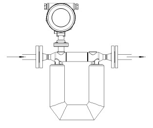
1.2.1 The shell is installed downward
If the fluid to be measured is a liquid, the sensor is generally mounted with the housing facing downward to prevent the air from accumulating in the sensor.
The vibrator is inside the tube so as to achieve the purpose of accurately measuring the mass flow. As shown in Figure 2-1:
 Â
Â
Figure 2-1 Enclosure facing down for liquids
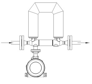
1.2.2 Housing Upward Installation
If the fluid to be measured is a gas, the sensor is generally installed with the housing facing upward to prevent the condensate from accumulating in the sensor vibrating tube. As shown in Figure 2-2:
 Â
Â
Figure 2-2 Enclosure facing up for gas
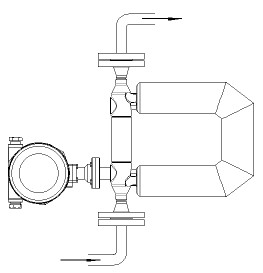
1.2. 3 Vertical pipe installation
If the fluid to be measured is a liquid, solid mixture, install the sensor on a vertical pipe.
This prevents particles from accumulating in the sensor tube. In addition, if the process pipeline needs to be cleaned with gas and steam, this installation method can also facilitate the cleaning, but this installation method is harder to fix than the former two, and the pressure loss is smaller. If the sensor is installed in a vertical pipe, the liquid and slurry should flow upward through the sensor. Gas may flow upwards or downwards. As shown in Figure 2-3:
 Â
Â
Figure 2-3 is installed on a vertical pipe and is suitable for slurry
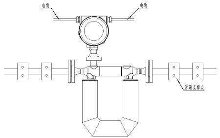
1.3 installation diagram sensorTypical installation of the sensor directly on the fluid process pipe, as shown in Figure 2-4:
 Â
Â
Figure 2-4 Typical installation
Â
note!
The sensor can measure bidirectional fluids, but in order for the flow transmitter to have the correct flow indication, it is recommended that the actual flow be consistent with the flow direction indication on the sensor housing.
*Skid(Chemical Dosing Skid) and package is fit both customer specification and international standards
* Both manual control & remote control can be as the optional.
* The integration system design, overcomes the defect of only the signal units.
* Customised design to meet of the requirement of different demand.
*All kinds of brand, material and parts can be available with different projects.
Chemical Industry Injection Package
Odm Chemical Industry Injection Package,Plastic Chemical Industry Injection Package,Plastic Industry Chemicals Injection Package,Chemical Dosing Skid
Zhejiang Ailipu Technology Co., LTD. , http://www.alipu.com