Baosteel Power Plant 1# 350MW Unit DEH/MEH Low-voltage Pure Electro-Control System Renovation
One.
Baosteel Power Plant 1#350MW unit is an intermediate reheat and double-cylinder double exhaust steam condensing unit produced by Mitsubishi Heavy Industries. The turbine control system was originally an electro-hydraulic co-existing low-pressure turbine oil system. The normal operation was based on ESC and the liquid was adjusted for backup. The tracking devices of the two sets of control systems are independent of each other and can track and switch to each other. The hydraulic adjustment adopts a rotary damping full-hydraulic adjustment system. The electric adjustment (MTM) is a set of analog electric adjustment device, which is used in conjunction with the hydraulic system to control the start and normal operation of the turbine.
Due to the long service life, aging equipment and lack of spare parts, in March and June 2002, the power plant overhauled the unit. During the overhaul, Xinhua Control Engineering Co., Ltd. modified the control system of the unit and changed the original regulation system to a low-voltage pure electric control system.
Second, the DEH / MEH system transformation 1. The DEH system was rebuilt to dismantle the original hydraulic backup system and the original analog ESC MTM was replaced by Xinhua DEH-IIIA. The DEH control system is shown in Figure 1.
There are two high-pressure main-valve oil engines, eight high-profile door oil engines, two medium-pressure main-valve oil engines, and two medium-adjust engine oil engines. All oil engines are not changed. According to the sequence of high-profile door opening, servo control system feedback and valve position indication requirements, valve activity test method requirements and the load capacity of the electro-hydraulic converter, the adjustment mode of the electro-hydraulic converter and the valve oil configuration after the system modification is: each The electro-hydraulic converter controls two oil motives, totaling six electro-hydraulic converters.
This configuration allows the unit to use the main valve start-up method. The sequence of the opening of the oil motive and the valve is regulated by the oil motor to facilitate the valve activity test. The medium-pressure main valve oil engine is a switch type and is controlled by safety oil.
High and Medium Pressure Governor Oil Motives The output control of each electrohydraulic converter is equipped with two OPC solenoid valves in parallel on the oil circuit. When the load rejection at the unit is over 103% of the rated speed, the OPC solenoid valve will act to shut down the high and medium pressure gates instantaneously. . A critical relay is set in each electro-hydraulic converter. When the safety oil is actuated, the oil control oil is drained to quickly close the high and medium pressure control door.
A valve position transmitter (LVDT) is installed on each adjustable throttle motor. This signal is sent to the DEH system to monitor the unit operating conditions.
The emergency breakers in the original security system, manual trip devices, emergency shutoff throttles, test slide valves, remote reset devices, and fuel injection test devices were retained. The combination of axial displacement, low lubricating oil pressure, low vacuum and electromagnetic tripping is eliminated, and shaft displacement, low oil pressure, and low vacuum are replaced with pressure switches.
In the safety oil roads controlling two medium-pressure main-valve oil engines, one more test solenoid valve is added, and the solenoid valve acts to cut off the safety oil and let the safety oil leaked to the oil engine be let go, allowing the oil motor to move. Close the medium pressure valve for full stroke activity testing.
2. The MEH system was rebuilt to replace the original BFPT with Xinhua MEH, retaining the small turbine in-place electro-hydraulic converter and oil motive.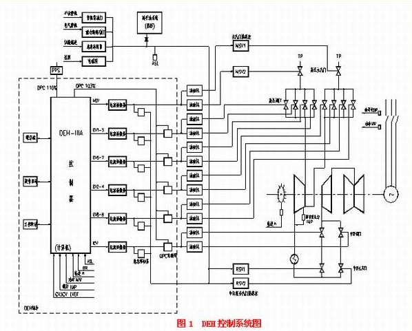 III. DEH/MEH system hardware and software design Baosteel 1# reconstruction The hardware configuration of DEH and MEH system mainly consists of engineering station, operator station (and communication interface station), basic control DPU, DPU of MEH, and various I/O cards. Parts, back-up hands, etc.
The entire system uses a two-tier network structure. The first layer uses Ethernet and the second layer uses Bitbus. The system is equipped with three MMI stations and three DPU stations. Each station and control DPU are connected by a redundant data highway. Each DPU control processing unit is connected to its I/O station via the redundant Bitbus industrial control network.
The basic control part of the DEH-IIIA consists of a pair of redundant DPUs and corresponding I/O control cards. Three speed measurement cards (MCP cards), two loop control cards (LC cards), two analog input cards (AI cards), and two digital input cards (DI cards) form the basic control signal input section. The DO card serves as a basic control switch output. The input I/O cards and important signals are all three-to-two redundant configurations. A hardware over-speed protection control (OPC) function block consists of three additional MCP cards (speed card), an over-speed protection card (OPC card), and an OPC terminal board. Six valve control cards (VCC cards) form part of the valve servo control system, and each VCC is used for the control of two valves.
A MEH consists of a pair of DPUs and an I/O station; the control of the two MEHs is independent and their configuration is exactly the same. I/O stations are mainly composed of speed cards, VCC cards, LC cards, DI cards, DO cards, etc. Terminal boards are arranged on the back of the cabinet.
Three human-machine interface stations are configured in the system, two are used as operator stations (and communication interface stations, and data communication between DEH and DCS systems is completed), and one is used as an engineer station.
The DEH system is equipped with a hard-manipulator disk to achieve manual back-up of the valve through a hardware connection in case of an accident and to maintain the unit's operation.
The DEH/MEH system software function is similar to that of a normal condensing unit, with speed control, automatic synchronization, load control, primary frequency modulation, coordinated control, vacuum limited load, valve switching and valve testing. Control methods include OA (operator auto), ATS (stress limit + program control curve), and APS (APC stress remote control). Among them, ATS and APS are steam turbine program control.
The simple stress calculation logic in the ATS is calculated by the DEH, and the ATS maintains the speed signal and the rate of change of the load. The ATS exits after the valve switching at the grid connection and returns to the automatic mode. In this mode, the speed-up process before grid-connection is performed automatically, and the target value and the rate of increase of the speed are automatically given, and the warm-up is performed automatically. After the grid connection with the initial load, the operator needs to give the final target value of the load.
The stress calculation in APS is completed by APC sequence control logic. APC automatically gives the unit's speed target and rate, and the initial load of network connection (5% or 10%), main valve/high-profile door switch command, DEH is only receiving and executing. APC instructions. The APS and DEH interfaces are switched and the DEH logic completes the analog switching.
Fourth, the valve servo control circuit As an electro-hydraulic converter controls two oil motives, making the use of oil motive displacement for servo loop feedback is inconvenient. The valve servo control loop is changed to hydraulic feedback. The principle is shown in Figure 2. DEH output signal to the VCC card, converted to valve position, power amplifier output to control the electro-hydraulic converter, the electrical signal is converted to control the oil pressure. The hydraulic pressure is controlled and converted into a voltage signal by a pressure transmitter. Feedback is compared with the valve position command. The difference between the two is proportionally amplified and then applied to the electro-hydraulic converter in the form of current (0-400 Ma), resulting in stable formation. The oil pressure is controlled and the oil motive is stable in the corresponding position.
Two oil displacements (LVDT) are sent to the power amplifier terminal block and into the DEH system to facilitate the inspection of the unit's operating conditions.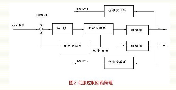 The output pressure of the large electro-mechanical hydraulic transducer is detected by a pressure transmitter. The transmitter is powered by the power amplifier terminal board (24VDC). The transmitter has a setting range of 0-0.4Mpa and 4-20mA output. The oil pressure range of the oil motive is 0.16-0.33Mpa, corresponding to 0-100% instruction in DEH.
The mechanical zero adjustment of the large electro-mechanical hydraulic converter is 0.12Mpa, that is, when the unit is reset, the DEH output command is 0, and the oil control oil pressure is 0.12Mpa. When the DEH output command gradually increases to 19.05%, the power amplifier board output current is about 50mA, corresponding to the valve control oil pressure is 0.16MPa, the high pressure control valve starts to open. Power amplifier board output current is about 250mA, adjust the door to open.
Small machine servo control loop principle is the same as large machine, its electro-hydraulic converter is the original equipment, pressure transmitter setting range is 0-0.4Mpa, 4-20mA output. The oil pressure range of the oil motive is 0.059-0.286 Mpa, corresponding to 0-100% instruction in MEH.
V. Overspeed Control and Overspeed Protection Special hardware is used to achieve speed control and protection functions. It consists of three speed cards (MCP cards), a hardware over-speed protection card (OPC) and an OPC terminal board (see Figure 3).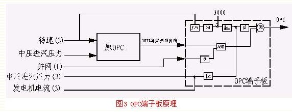 The three speed cards respectively detect the speed signals from the three speed probes and send signals with speeds greater than 103% and 110%. The OPC card sends 103% and 110% signals to the OPC terminal board after selecting two of the three hardware, and finally generates the OPC signal to control the OPC solenoid valve. If the speed exceeds 110%, an AST stop signal is sent to the ETS system to shut down the turbine.
Three-way speed, three-way medium pressure steam inlet pressure and three-way generator current input OPC terminal board (three out of two), for turbine speeding, turbine mechanical power and generator power unbalanced discrimination. The power imbalance signal is superimposed on the turbine speed signal. The OPC action point is shown in Figure 4. If the speed is greater than 3210 RPM, or if the power imbalance is more than 60%, the OPC will immediately act. In other cases, the overlay is shown in the diagonal line.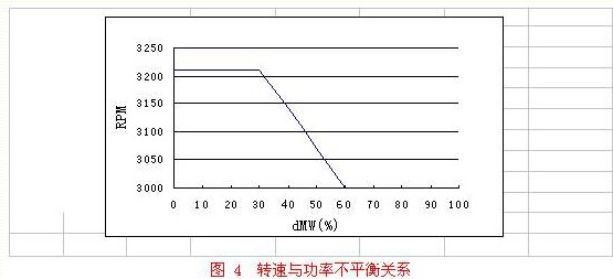 The DPU software also has an overspeed control function. When the speed is increased, the door is turned off and used for overspeed control, but it functions at a slower speed than hardware. In summary, the OPC implementation functions are as follows:
· Over speed protection 103% (107%): Before the grid connection, when the turbine speed exceeds 103% of the rated speed; after the grid connection, when the speed exceeds 107% of the rated speed (103% is shielded), the DEH immediately issues an instruction through the electricity. Liquid converter and OPC solenoid valve, fast closing high and medium pressure regulating door.
• 110% speeding: When the turbine speed exceeds 110%, a stop command is issued and all valves are closed quickly to stop the unit.
· Load rejection pre-adjustment door: When the load is more than 30%, the unit speed has not risen before the OPC protection operation speed at the moment of load rejection. The DEH closes the high and middle pressure control door in advance to play an effective overspeed protection function.
Instant load rejection control: If the generator power is suddenly reduced and the difference between the turbine power and the generator power exceeds the preset value, the DEH quickly closes the high and medium pressure regulating gate to reduce the turbine power, thereby reducing the maximum dynamic angle of the power grid and improving the stability of the power grid. Sex.
• Overspeed test: 103%, 107%, 110% and mechanical overspeed tests are easily and safely performed by DEH.
VI. DEH and DCS System Communication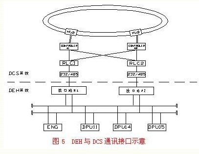 DCS is the Westinghouse OVATION system. To realize operation integration, the DEH/MEH control system is operated, monitored, and alarmed on the DCS operator station. The DEH and DCS communication interface design is shown in Figure 5.
The DEH communication interface station, DCS side 232/485 converter, RLC card and controller are all redundantly configured, which realizes the redundancy of DEH and DCS communication and ensures the safe and reliable operation of the unit.
The DEH side communication interface software runs on the communication interface station, and the adopted network communication protocol is the Modbus protocol. The DEH terminal serves as a slave station, the DCS terminal serves as a master station, and the slave station DEH terminal executes an instruction from the DCS terminal and sends the relevant data to the DCS terminal for display. The communication is normal and can meet the operation requirements, but the data transmission speed of the serial communication mode is slow.
7. The unit started to put into operation 1# 350MW transformation unit of Baosteel Power Plant. On the evening of June 8, it successfully turned 3000RPM for the first time. On the 10th, the second time it succeeded in making a successful turn. After that, it performed electrical tests and connected the network with load warming. Decommissioning for overspeed test (103% overspeed test, 107% overspeed test, mechanical overspeed test), successively performed valve switching, power loop switching, pressure regulating circuit switching, valve loosening test and coordinated control test, and put into the vacuum limit load , high and low load limits and other functions. APS, ATS, and OA methods were used to achieve success. On June 21st, the 50% load test of this unit was successful and the maximum speed was 3089 RPM. The retrofitted DEH system has fast response time and high control accuracy, and all indicators are better than the original regulation system.
The successful commissioning of low-voltage pure ESC of 350MW units in Baosteel Power Plant can provide reference for the reconstruction of similar units.
Baosteel Power Plant 1#350MW unit is an intermediate reheat and double-cylinder double exhaust steam condensing unit produced by Mitsubishi Heavy Industries. The turbine control system was originally an electro-hydraulic co-existing low-pressure turbine oil system. The normal operation was based on ESC and the liquid was adjusted for backup. The tracking devices of the two sets of control systems are independent of each other and can track and switch to each other. The hydraulic adjustment adopts a rotary damping full-hydraulic adjustment system. The electric adjustment (MTM) is a set of analog electric adjustment device, which is used in conjunction with the hydraulic system to control the start and normal operation of the turbine.
Due to the long service life, aging equipment and lack of spare parts, in March and June 2002, the power plant overhauled the unit. During the overhaul, Xinhua Control Engineering Co., Ltd. modified the control system of the unit and changed the original regulation system to a low-voltage pure electric control system.
Second, the DEH / MEH system transformation 1. The DEH system was rebuilt to dismantle the original hydraulic backup system and the original analog ESC MTM was replaced by Xinhua DEH-IIIA. The DEH control system is shown in Figure 1.
There are two high-pressure main-valve oil engines, eight high-profile door oil engines, two medium-pressure main-valve oil engines, and two medium-adjust engine oil engines. All oil engines are not changed. According to the sequence of high-profile door opening, servo control system feedback and valve position indication requirements, valve activity test method requirements and the load capacity of the electro-hydraulic converter, the adjustment mode of the electro-hydraulic converter and the valve oil configuration after the system modification is: each The electro-hydraulic converter controls two oil motives, totaling six electro-hydraulic converters.
This configuration allows the unit to use the main valve start-up method. The sequence of the opening of the oil motive and the valve is regulated by the oil motor to facilitate the valve activity test. The medium-pressure main valve oil engine is a switch type and is controlled by safety oil.
High and Medium Pressure Governor Oil Motives The output control of each electrohydraulic converter is equipped with two OPC solenoid valves in parallel on the oil circuit. When the load rejection at the unit is over 103% of the rated speed, the OPC solenoid valve will act to shut down the high and medium pressure gates instantaneously. . A critical relay is set in each electro-hydraulic converter. When the safety oil is actuated, the oil control oil is drained to quickly close the high and medium pressure control door.
A valve position transmitter (LVDT) is installed on each adjustable throttle motor. This signal is sent to the DEH system to monitor the unit operating conditions.
The emergency breakers in the original security system, manual trip devices, emergency shutoff throttles, test slide valves, remote reset devices, and fuel injection test devices were retained. The combination of axial displacement, low lubricating oil pressure, low vacuum and electromagnetic tripping is eliminated, and shaft displacement, low oil pressure, and low vacuum are replaced with pressure switches.
In the safety oil roads controlling two medium-pressure main-valve oil engines, one more test solenoid valve is added, and the solenoid valve acts to cut off the safety oil and let the safety oil leaked to the oil engine be let go, allowing the oil motor to move. Close the medium pressure valve for full stroke activity testing.
2. The MEH system was rebuilt to replace the original BFPT with Xinhua MEH, retaining the small turbine in-place electro-hydraulic converter and oil motive.
The entire system uses a two-tier network structure. The first layer uses Ethernet and the second layer uses Bitbus. The system is equipped with three MMI stations and three DPU stations. Each station and control DPU are connected by a redundant data highway. Each DPU control processing unit is connected to its I/O station via the redundant Bitbus industrial control network.
The basic control part of the DEH-IIIA consists of a pair of redundant DPUs and corresponding I/O control cards. Three speed measurement cards (MCP cards), two loop control cards (LC cards), two analog input cards (AI cards), and two digital input cards (DI cards) form the basic control signal input section. The DO card serves as a basic control switch output. The input I/O cards and important signals are all three-to-two redundant configurations. A hardware over-speed protection control (OPC) function block consists of three additional MCP cards (speed card), an over-speed protection card (OPC card), and an OPC terminal board. Six valve control cards (VCC cards) form part of the valve servo control system, and each VCC is used for the control of two valves.
A MEH consists of a pair of DPUs and an I/O station; the control of the two MEHs is independent and their configuration is exactly the same. I/O stations are mainly composed of speed cards, VCC cards, LC cards, DI cards, DO cards, etc. Terminal boards are arranged on the back of the cabinet.
Three human-machine interface stations are configured in the system, two are used as operator stations (and communication interface stations, and data communication between DEH and DCS systems is completed), and one is used as an engineer station.
The DEH system is equipped with a hard-manipulator disk to achieve manual back-up of the valve through a hardware connection in case of an accident and to maintain the unit's operation.
The DEH/MEH system software function is similar to that of a normal condensing unit, with speed control, automatic synchronization, load control, primary frequency modulation, coordinated control, vacuum limited load, valve switching and valve testing. Control methods include OA (operator auto), ATS (stress limit + program control curve), and APS (APC stress remote control). Among them, ATS and APS are steam turbine program control.
The simple stress calculation logic in the ATS is calculated by the DEH, and the ATS maintains the speed signal and the rate of change of the load. The ATS exits after the valve switching at the grid connection and returns to the automatic mode. In this mode, the speed-up process before grid-connection is performed automatically, and the target value and the rate of increase of the speed are automatically given, and the warm-up is performed automatically. After the grid connection with the initial load, the operator needs to give the final target value of the load.
The stress calculation in APS is completed by APC sequence control logic. APC automatically gives the unit's speed target and rate, and the initial load of network connection (5% or 10%), main valve/high-profile door switch command, DEH is only receiving and executing. APC instructions. The APS and DEH interfaces are switched and the DEH logic completes the analog switching.
Fourth, the valve servo control circuit As an electro-hydraulic converter controls two oil motives, making the use of oil motive displacement for servo loop feedback is inconvenient. The valve servo control loop is changed to hydraulic feedback. The principle is shown in Figure 2. DEH output signal to the VCC card, converted to valve position, power amplifier output to control the electro-hydraulic converter, the electrical signal is converted to control the oil pressure. The hydraulic pressure is controlled and converted into a voltage signal by a pressure transmitter. Feedback is compared with the valve position command. The difference between the two is proportionally amplified and then applied to the electro-hydraulic converter in the form of current (0-400 Ma), resulting in stable formation. The oil pressure is controlled and the oil motive is stable in the corresponding position.
Two oil displacements (LVDT) are sent to the power amplifier terminal block and into the DEH system to facilitate the inspection of the unit's operating conditions.
The mechanical zero adjustment of the large electro-mechanical hydraulic converter is 0.12Mpa, that is, when the unit is reset, the DEH output command is 0, and the oil control oil pressure is 0.12Mpa. When the DEH output command gradually increases to 19.05%, the power amplifier board output current is about 50mA, corresponding to the valve control oil pressure is 0.16MPa, the high pressure control valve starts to open. Power amplifier board output current is about 250mA, adjust the door to open.
Small machine servo control loop principle is the same as large machine, its electro-hydraulic converter is the original equipment, pressure transmitter setting range is 0-0.4Mpa, 4-20mA output. The oil pressure range of the oil motive is 0.059-0.286 Mpa, corresponding to 0-100% instruction in MEH.
V. Overspeed Control and Overspeed Protection Special hardware is used to achieve speed control and protection functions. It consists of three speed cards (MCP cards), a hardware over-speed protection card (OPC) and an OPC terminal board (see Figure 3).
Three-way speed, three-way medium pressure steam inlet pressure and three-way generator current input OPC terminal board (three out of two), for turbine speeding, turbine mechanical power and generator power unbalanced discrimination. The power imbalance signal is superimposed on the turbine speed signal. The OPC action point is shown in Figure 4. If the speed is greater than 3210 RPM, or if the power imbalance is more than 60%, the OPC will immediately act. In other cases, the overlay is shown in the diagonal line.
· Over speed protection 103% (107%): Before the grid connection, when the turbine speed exceeds 103% of the rated speed; after the grid connection, when the speed exceeds 107% of the rated speed (103% is shielded), the DEH immediately issues an instruction through the electricity. Liquid converter and OPC solenoid valve, fast closing high and medium pressure regulating door.
• 110% speeding: When the turbine speed exceeds 110%, a stop command is issued and all valves are closed quickly to stop the unit.
· Load rejection pre-adjustment door: When the load is more than 30%, the unit speed has not risen before the OPC protection operation speed at the moment of load rejection. The DEH closes the high and middle pressure control door in advance to play an effective overspeed protection function.
Instant load rejection control: If the generator power is suddenly reduced and the difference between the turbine power and the generator power exceeds the preset value, the DEH quickly closes the high and medium pressure regulating gate to reduce the turbine power, thereby reducing the maximum dynamic angle of the power grid and improving the stability of the power grid. Sex.
• Overspeed test: 103%, 107%, 110% and mechanical overspeed tests are easily and safely performed by DEH.
VI. DEH and DCS System Communication
The DEH communication interface station, DCS side 232/485 converter, RLC card and controller are all redundantly configured, which realizes the redundancy of DEH and DCS communication and ensures the safe and reliable operation of the unit.
The DEH side communication interface software runs on the communication interface station, and the adopted network communication protocol is the Modbus protocol. The DEH terminal serves as a slave station, the DCS terminal serves as a master station, and the slave station DEH terminal executes an instruction from the DCS terminal and sends the relevant data to the DCS terminal for display. The communication is normal and can meet the operation requirements, but the data transmission speed of the serial communication mode is slow.
7. The unit started to put into operation 1# 350MW transformation unit of Baosteel Power Plant. On the evening of June 8, it successfully turned 3000RPM for the first time. On the 10th, the second time it succeeded in making a successful turn. After that, it performed electrical tests and connected the network with load warming. Decommissioning for overspeed test (103% overspeed test, 107% overspeed test, mechanical overspeed test), successively performed valve switching, power loop switching, pressure regulating circuit switching, valve loosening test and coordinated control test, and put into the vacuum limit load , high and low load limits and other functions. APS, ATS, and OA methods were used to achieve success. On June 21st, the 50% load test of this unit was successful and the maximum speed was 3089 RPM. The retrofitted DEH system has fast response time and high control accuracy, and all indicators are better than the original regulation system.
The successful commissioning of low-voltage pure ESC of 350MW units in Baosteel Power Plant can provide reference for the reconstruction of similar units.
yangdong is a large engine factory for Diesel Generator sets, the machine technology is mature, stable, long-term as used by domesitic and worldwide customer.
Yangdong Diesel Generator is good at small power, its power range from 8-80kw,prime power and standby power.
Our diesel generator factory is in Jiangsu Province, China, is a Factory with OEM service.


Yangdong Diesel Generator
Yangdong Diesel Generator,Yangdong Power Generator,38Kw Yangdong Diesel Generator,25Kva Power Generator
Jiangsu Province Suanma Power Equipment Co., Ltd. , http://www.suanma-generator.com